

Inside Boeing’s Drafting Rooms: How Engineers Designed Airplanes by Hand
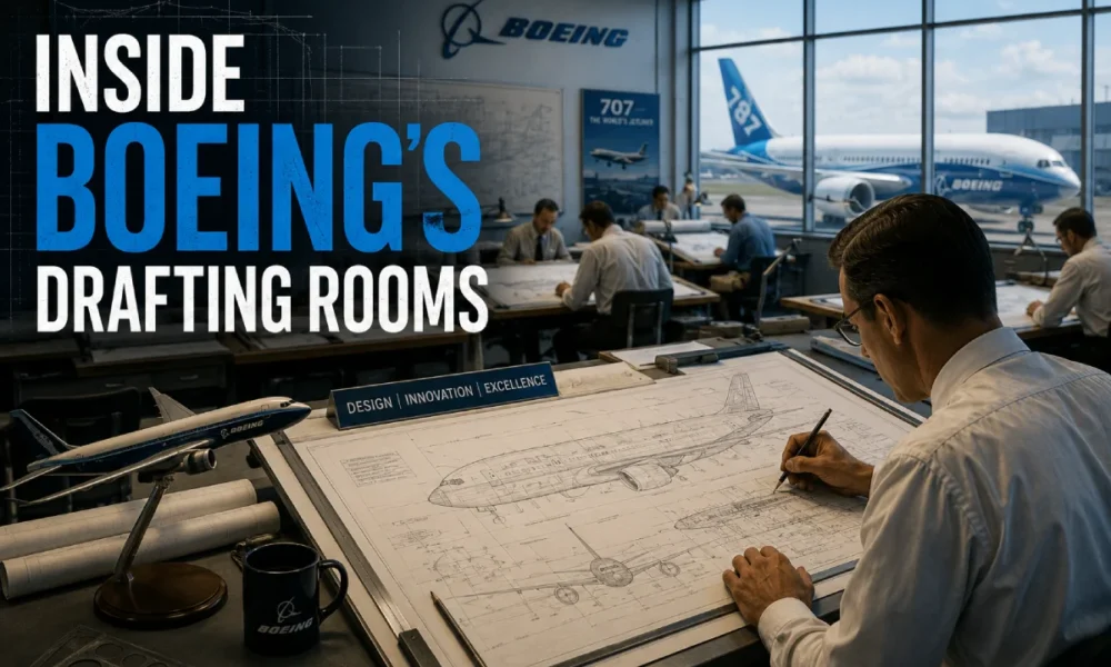
Before a single Boeing jet ever left the ground, it existed on paper — drawn, checked, and re-drawn by hand in rooms full of slanted tables and slide rules. For most of the company’s first eighty years, this was how airplanes got made: not in a CAD program, but on a drafting board.
Table Of Content
- Where It Started: The Red Barn
- What a Mid-Century Drafting Room Actually Looked Like
- Lofting: How Boeing Kept Curves Consistent Across an Entire Airplane
- The “Boeing Wonderland”: Camouflaging Plant 2 in Plain Sight
- Why the Drafting Room Disappeared: The Boeing 777 and CATIA
- What Boeing’s Drafting Rooms Looked Like, By the Numbers
- Frequently Asked Questions
- What is “lofting” in aircraft design?
- What were the lead weights called “ducks” used for?
- When did Boeing stop using manual drafting rooms?
- Can you still see a Boeing drafting room today?
- Is the “Boeing Wonderland” rooftop camouflage a documented historical fact?
- The Bottom Line
The story of Boeing’s drafting rooms is really the story of how the company solved a hard problem — how do you get thousands of separate hand-drawn parts to fit together into one flying machine — long before computers could do the math for you. That problem shaped everything from wartime camouflage on the factory roof to a lead weight nicknamed a “duck.” Here’s what actually happened in those rooms, and how the whole system eventually gave way to a keyboard and a screen.
Where It Started: The Red Barn
Boeing’s very first drafting room wasn’t in a purpose-built office tower. It was on the second floor of a converted boat shed on the Duwamish River in Seattle — a building everyone now calls the Red Barn.
William Boeing bought the old Heath Shipyard site in 1910, and by 1916 he’d incorporated the Pacific Aero Products Company (renamed Boeing Airplane Company a year later) to build his first aircraft there. As the business grew, so did the barn. Historical records from the City of Tukwila’s landmarks commission describe how, in late 1916 or early 1917, the building was expanded with a second floor — roughly a third of the new space became offices, and the rest went to open manufacturing area. By the time Boeing landed a Navy contract for 50 training planes in 1917, the upper floor housed the engineering department, a drafting room, and an experimental lab, while machinists worked wood and propellers below.
This wasn’t a large operation by later standards. But it set the template Boeing would use for decades: engineering and drafting stacked directly above (or beside) the factory floor, so a drawing could get from a drafter’s table to a machinist’s bench in minutes, not days.
The Red Barn served as Boeing’s home base until 1936, when the larger Plant 2 opened. It was nearly torn down in the 1970s after decades of decay, but preservationists saved it — the building was barged down the river in 1975 and now anchors the Museum of Flight in Seattle, where a recreated drafting room with period tools is still on display.
What a Mid-Century Drafting Room Actually Looked Like
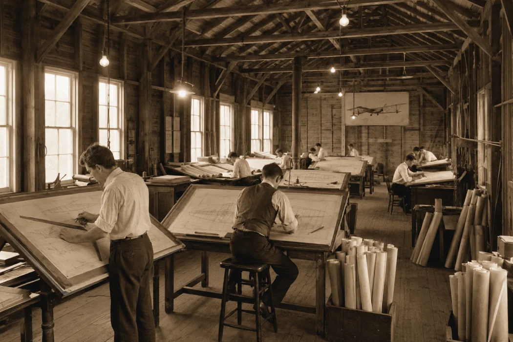
By the 1940s and ’50s, Boeing’s drafting operation had scaled up dramatically to meet wartime demand, and the workspace itself changed shape. Gone was the cozy second floor of a barn. In its place: long halls lined with row after row of slanted drafting tables, each staffed by a drafter working with T-squares, triangles, and mechanical pencils.
A few tools defined the era:
- Slide rules handled the math — multiplication, division, trigonometry — before pocket calculators existed.
- French curves and flexible splines let drafters draw smooth, non-circular curves by hand.
- Vellum and linen tracing paper were the standard drawing surfaces, since they held up to repeated handling and could be reproduced as blueprints.
The work was physically demanding and visually repetitive — one engineer might spend weeks refining a single wing rib profile. Coordination across a project this size required strict discipline: master layout drawings, version-controlled revisions, and a paper trail that had to stay perfectly synced across departments, because a landing gear drawn by one team had to fit precisely into a wheel well drawn by another, sometimes in a different building entirely.
Lofting: How Boeing Kept Curves Consistent Across an Entire Airplane
The hardest problem in aircraft drafting has never been straight lines — it’s curves. A wing, fuselage, or nacelle has to keep the same smooth aerodynamic shape whether you’re looking at drawing number one or drawing number two hundred, and every part fabricated from those drawings has to match up with the part next to it.
The technique Boeing and every other manufacturer used to solve this is called lofting, a term borrowed from wooden shipbuilding, where hull curves were laid out full-scale in a loft space above the factory floor. According to a detailed technical breakdown from AirCorps Aviation, which restores and documents historic aircraft, loft drawings were made at full scale, often on large sheets of metal or wood, and held to tolerances as tight as 0.007 inches. That’s the kind of precision that let Boeing guarantee every aircraft off a given production line had an identical outer profile — critical when you’re bolting together parts built at different plants.
The physical process worked like this: engineers connected key cross-section points using long, flexible strips of wood or plastic called splines, bent by hand until they traced a smooth curve through the points. To hold a spline in place while a drafter traced its path, they used small pointed lead weights known as “ducks” — the aerospace engineering term of art, documented in university coursework on aircraft configuration layout, not just Boeing folklore. You’ll sometimes see period photos of engineers lying flat on a factory floor, working together over one enormous full-scale drawing. That’s lofting in action — and it’s exactly as labor-intensive as it looks.
Lofting had real limits. It took trial and error to get a curve smooth in both cross-section and along its length, and there was no single mathematical definition of the surface — just the physical drawing itself. That weakness became a wartime liability: full-scale master templates stored in one hangar were a single-point failure. A design historian writing about the era notes that North American Aviation (whose engineering legacy later folded into Boeing through mergers) pushed lofting toward pure mathematics during WWII specifically so critical geometry could be captured in numeric tables instead of vulnerable physical blueprints — an early, analog step toward the digital modeling that would eventually replace lofting altogether.
The “Boeing Wonderland”: Camouflaging Plant 2 in Plain Sight
Boeing’s drafting rooms weren’t just work spaces — during World War II, they were strategic targets. Plant 2, where much of Boeing’s wartime engineering and production happened, was a known objective for enemy bombers, given its role churning out B-17 Flying Fortresses.
To disguise it, the U.S. military worked with Boeing to build an elaborate rooftop camouflage installation over the plant — fake streets, houses, and trees designed to make the facility look like an ordinary residential neighborhood from the air. It’s popularly nicknamed “Boeing Wonderland” in historical retrospectives on the era, though it’s worth being upfront that detailed primary-source documentation of this specific rooftop camouflage (materials, scale, exact dates) is thinner online than the core Red Barn and Plant 1 history — most of what circulates today comes from secondary accounts rather than Boeing’s own archives, so treat the finer details as historically plausible but not fully pinned down.
What is well documented is the stakes: the drafting rooms and shop floors underneath were producing aircraft that were directly shaping the outcome of the war, which is exactly why protecting them mattered enough to justify that kind of elaborate deception.
Why the Drafting Room Disappeared: The Boeing 777 and CATIA
The era of the massive manual drafting room didn’t end with a single announcement — but if you had to pick one project that marked the turning point, it’s the Boeing 777.
Launched in the early 1990s, the 777 became the first commercial jetliner designed 100 percent digitally, using three-dimensional solid modeling instead of pencil and vellum. Boeing signed a liaison agreement with IBM and Dassault Systèmes in April 1991 to use CATIA (Computer-Aided Three-dimensional Interactive Application), a French-developed 3D design system, alongside a Boeing-built analysis tool called ELFINI. Instead of drawings on paper, engineers built and stored their work across a network of linked IBM mainframes — at the time, one of the largest mainframe installations of its kind, connecting roughly 1,700 workstations in the Puget Sound area alone to sites in Japan, Wichita, and Philadelphia.
The payoff was concrete, not just theoretical. Boeing was initially skeptical that a fully digital design would actually work, so the company built one physical mock-up — the nose section — specifically to check CATIA’s results against reality. According to Wikipedia’s account of the program, the test went well enough that Boeing canceled every other planned mock-up, something no prior commercial jetliner program had done. As Larry Olson, then Boeing’s information systems director for Commercial Airplane Group, put it at the time:
“100 percent digital design was a real paradigm shift… The 777 was completed with such precision that it was the first Boeing jet that didn’t need its kinks worked out on an expensive physical mock-up plane.”
Boeing also built a digital human model, nicknamed CATIA Man (and later “Humod”), to simulate a mechanic climbing inside the virtual airplane. One early catch: the simulation revealed a real human mechanic wouldn’t be able to physically reach a navigation light on the plane’s roof to change a bulb — a fix that was far cheaper to make on a screen than to discover after the aircraft was already flying.
That single project effectively retired the drafting board as Boeing’s primary design tool. The skills didn’t vanish overnight, and lofting principles still inform how curves get modeled in CAD systems today — but the room full of slanted tables and slide rules was gone.
What Boeing’s Drafting Rooms Looked Like, By the Numbers
Here’s a quick side-by-side of how the process changed across three eras of Boeing engineering.
| Era | Primary Tool | Design Medium | Curve Method | Physical Mock-Up Needed? |
|---|---|---|---|---|
| Red Barn (1917–1936) | Manual drafting board | Paper/vellum | Hand-drawn full-scale lofting | Yes |
| Mid-century (1940s–1980s, B-17/747-era) | Drafting table, slide rule | Vellum, tracing linen | Splines held by lead “ducks” | Yes |
| 777 program (1990s–present) | CATIA / 3D CAD workstation | Digital 3D solid model | Mathematically defined surfaces | No (nose section only, to validate) |
Frequently Asked Questions
What is “lofting” in aircraft design?
Lofting is the technique used to draw a curved aircraft surface — like a wing or fuselage — at full scale, so that every part built from the drawing matches the same profile. It originated in wooden shipbuilding, where hull curves were laid out in a loft above the shop floor, and aerospace engineers adapted it directly.
What were the lead weights called “ducks” used for?
Ducks were small, pointed lead weights drafters used to pin a flexible spline (a thin strip of wood or plastic) in place while tracing a smooth curve through a series of marked points on a lofting drawing.
When did Boeing stop using manual drafting rooms?
There wasn’t a single cutoff date, but the Boeing 777 program in the early 1990s is generally treated as the turning point — it was the first commercial jetliner designed entirely with 3D digital modeling (CATIA), which eliminated the need for full-scale paper drafting and physical mock-ups.
Can you still see a Boeing drafting room today?
Yes. The Museum of Flight in Seattle, built around the preserved Red Barn (Boeing’s original Plant 1 building), includes a recreated drafting room with period tools as part of its permanent exhibits.
Is the “Boeing Wonderland” rooftop camouflage a documented historical fact?
The broad claim — that Boeing’s Plant 2 was disguised from the air during WWII to protect it from bombing raids — is consistent with well-known Pacific Northwest wartime history. However, granular details about this specific installation are less rigorously documented in easily accessible sources than the Red Barn’s history, so it’s fair to treat specifics as reasonably well-established but not exhaustively sourced.
The Bottom Line
Boeing’s drafting rooms weren’t just where airplanes got drawn — they were a manufacturing system in their own right, built around discipline, physical craftsmanship, and a set of hand techniques (lofting especially) that had to be precise enough to keep thousands of separately built parts compatible. That system worked for the better part of a century, through the B-17, the 707, and the 747. It took a genuine technological leap — CATIA and full 3D digital modeling on the 777 — to finally retire it.
If you want to see the real thing rather than just read about it, the Museum of Flight in Seattle is the place to go: the Red Barn where it all started is still standing, drafting room and all.
Have questions about a specific era of Boeing’s engineering history, or want the FAQ section expanded with sourced answers on other Boeing topics? Let me know what to dig into next.